

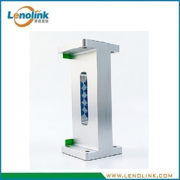
13.75–14.5 GHz WR75 Waveguide Bandpass Filter
Product Model: ZLWGBPF14P2E800R75I80C
Applications
Ku-Band Microwave & RF Applications
The Lenolink waveguide bandpass filter is suitable for:
- Microwave communication systems
- Radar and RF sensing systems
- Satellite communication equipment
- Microwave antenna systems
- RF front-end systems
- Microwave test and measurement equipment
- RF signal filtering systems
- Microwave transceiver systems
- High-frequency RF subsystems
- Laboratory microwave equipment
- Microwave radio systems
- RF front-end modules
- Waveguide transmission assemblies
- Satellite ground equipment
- Microwave backhaul systems
Typical Applications
Microwave Signal Filtering
Used to pass the required 13.75–14.5 GHz microwave signals while suppressing unwanted signals outside the passband.
Radar & RF Systems
Suitable for RF front-end and microwave signal conditioning applications where frequency selectivity is important.
Microwave Test Equipment
Can be integrated into microwave measurement and test systems requiring a defined passband and high stopband rejection.
Antenna & Waveguide Systems
Designed for integration into compatible waveguide transmission paths.
Product Summary
The Lenolink ZLWGBPF14P2E800R75I80C is a high-performance waveguide bandpass filter designed for microwave and RF systems operating from 13.75 to 14.5 GHz.
The filter provides a defined microwave passband while suppressing unwanted signals outside the operating frequency range. Its waveguide construction offers low insertion loss, high frequency selectivity and reliable mechanical performance for demanding microwave applications.
The filter features a 13.75–14.5 GHz passband, 750 MHz bandwidth, ≤0.2 dB insertion loss and ≥55 dB band suppression at 12.25–12.75 GHz.
The filter uses a BJ120 waveguide interface with M4 threaded mounting holes and an aluminum alloy housing, making it suitable for integration into microwave communication, radar, antenna and RF test systems.
Key RF specifications include:
- Frequency: 13.75–14.5 GHz
- Passband bandwidth: 750 MHz
- Waveguide type: WR75
- Flange configuration: BJ120
- Insertion loss: ≤0.2 dB
- Return loss: ≥20 dB
- Band suppression: ≥55 dB @ 12.25–12.75 GHz
- Material: Aluminum alloy
- Operating temperature: -40°C to +90°C
- Storage temperature: -50°C to +110°C
The compact waveguide structure supports reliable integration into microwave communication, RF, radar and test systems.
Key Features
- 13.75–14.5 GHz Ku-band operation
- WR75 rectangular waveguide interface
- BJ120 flange configuration
- 750 MHz Passband Bandwidth
- Low insertion loss ≤0.2 dB
- Return loss ≥20 dB
- High out-of-band suppression
- ≥55 dB suppression @ 12.25–12.75 GHz
- Aluminum alloy construction
- Operating temperature: -40°C to +90°C
- Storage temperature: -50°C to +110°C
- Compact waveguide filter structure
- Suitable for professional microwave and RF systems
- Customized waveguide filter solutions available
Technical Advantages
Low Insertion Loss
With insertion loss of ≤0.2 dB, the ZLWGBP14P2E800R75I80C is designed to minimize signal attenuation within the specified passband.
Defined Microwave Passband
The filter provides a defined operating frequency range from 13.75 to 14.5 GHz, corresponding to a 750 MHz passband.
High Out-of-Band Suppression
The filter provides band suppression of ≥55 dB at 12.25–12.75 GHz, helping reduce unwanted signals outside the specified operating band.
Waveguide Mechanical Interface
The filter uses a BJ120 waveguide interface with M4 threaded mounting holes, providing a standardized mechanical interface for compatible microwave systems.
Wide Temperature Capability
The aluminum alloy construction supports an operating temperature range of -40°C to +90°C, allowing integration into a wide range of microwave equipment and RF systems.
Technical Specifications
| Parameter | Specification |
|---|---|
| Model | ZLWGBPF14P2E800R75I80C |
| Frequency Range | 13.75–14.5 GHz |
| Passband Bandwidth | 750 MHz |
| Insertion Loss | ≤0.2 dB |
| Return Loss | ≥20 dB |
| Band Suppression | ≥55 dB @ 12.25–12.75 GHz |
| Waveguide Interface | WR75/BJ120 |
| Mounting Interface | M4 threaded holes |
| Material | Aluminum Alloy |
| Operating Temperature | -40°C to +90°C |
| Storage Temperature | -50°C to +110°C |
Note: Product specifications may vary according to the final engineering configuration and customer requirements.
Mechanical Specifications
The ZLWGBPF14P2E800R75I80C features a compact WR75 waveguide structure with a BJ120 flange interface and four M4 threaded mounting holes.
Based on the supplied mechanical drawing:
Material: Aluminum alloy
Flange size: 38 × 38 mm
Overall length: 80 mm
Mounting holes: 4 × M4 threaded holes
Waveguide interface: WR75 / BJ120
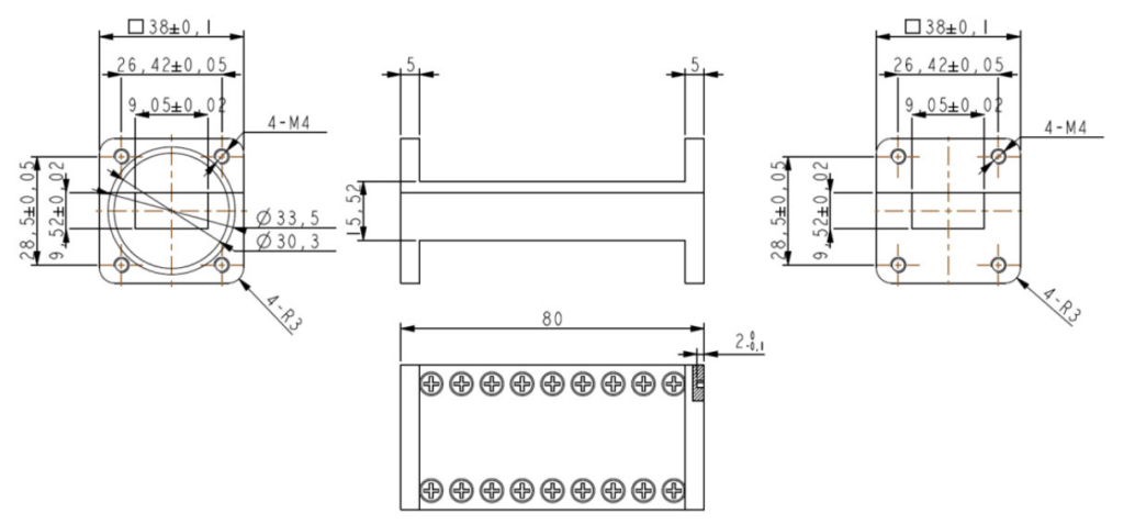
Note: Please refer to the latest engineering drawing for exact dimensions, tolerances and mounting details.
Waveguide Bandpass Filter Working Principle
How Does a Waveguide Bandpass Filter Work?
A waveguide bandpass filter is a passive microwave component designed to allow a specified frequency range to pass while attenuating frequencies outside the required passband.
The ZLWGBPF14P2E800R75I80C uses a precision-machined waveguide filter structure to achieve frequency-selective RF transmission.
Within the specified 13.75–14.5 GHz passband, microwave signals are transmitted with low insertion loss.
Outside the passband, the filter attenuates unwanted signals according to its rejection characteristics.
This makes waveguide bandpass filters useful for:
- Frequency selection
- Out-of-band interference suppression
- Microwave signal conditioning
- RF front-end filtering
- Radar signal processing
- Communication system frequency management
Why Choose Lenolink Waveguide Bandpass Filter?
Professional RF & Microwave Component Manufacturer
Lenolink provides passive RF and microwave components for telecommunications, wireless infrastructure, microwave systems and RF test applications.
Our product portfolio includes:
- Waveguide filters
- Waveguide components
- Waveguide-to-coaxial adapters
- RF filters
- RF combiners
- Duplexers
- Hybrid couplers
- RF dummy loads
- DAS passive components
- Customized RF and microwave components
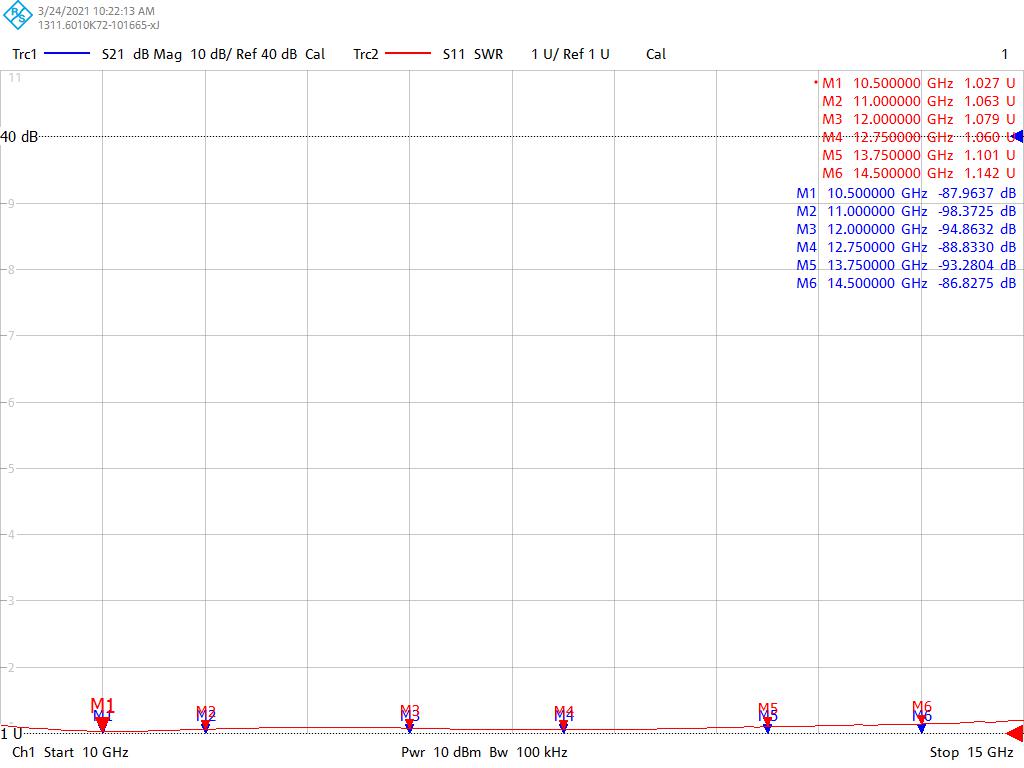
Low-Loss Microwave Filter Design
The ZLWGBPF14P2E800R75I80C provides insertion loss of ≤0.2 dB, helping minimize attenuation within the specified Ku-band passband.
This makes the filter suitable for microwave systems where signal loss and RF link budget are important considerations.
High Frequency Selectivity
The filter provides a defined 13.75–14.5 GHz passband and specified suppression of ≥55 dB at 12.25–12.75 GHz, helping reduce unwanted signals outside the required operating band.
WR75 Microwave Interface
The WR75 waveguide interface and BJ120 flange configuration allow the filter to be integrated with compatible waveguide components and microwave assemblies.
Custom RF & Microwave Solutions
Different microwave systems may require different filter characteristics.
Lenolink can evaluate customized waveguide filter solutions based on:
- Frequency range
- Passband bandwidth
- Stopband requirements
- Rejection level
- Insertion loss
- Return loss
- Waveguide type
- Flange configuration
- Mechanical dimensions
- Mounting structure
- Material and surface finish
Waveguide Filter vs. Waveguide-to-Coaxial Adapter
A waveguide bandpass filter and a waveguide-to-coaxial adapter serve different functions.
The ZLWGBPF14P2E800R75I80C is a frequency-selective microwave filter. Its primary function is to pass the required frequency range while suppressing unwanted frequencies.
A waveguide-to-coaxial adapter, such as the Lenolink ZLR75SKL, is primarily used to transition RF signals between a WR75 waveguide and an SMA coaxial interface.
Simple Comparison
| Product | Main Function |
| Waveguide Bandpass Filter | Selects the required frequency band and rejects unwanted signals |
| Waveguide-to-Coaxial Adapter | Converts between waveguide and coaxial RF interfaces |
This distinction is important when selecting the correct microwave component for a system.
Need to select or reject specific frequencies? Choose a waveguide filter.
Need to connect a waveguide system to coaxial equipment? Choose a waveguide-to-coaxial adapter.
Frequently Asked Questions
Q1: What is a waveguide bandpass filter?
A waveguide bandpass filter is a passive microwave component designed to pass a specified frequency range while attenuating unwanted frequencies outside the passband.
Waveguide filters are widely used in microwave communication, radar, RF testing, antenna systems and other high-frequency applications.
Q2: What frequency range does the ZLWGBPF14P2E800R75I80C support?
The specified passband is 13.75–14.5 GHz.
Q3: What is the bandwidth of this waveguide filter?
The specified passband extends from 13.75 to 14.5 GHz, providing a 750 MHz passband bandwidth.
Q4: What waveguide type is used?
The filter uses a WR75 rectangular waveguide interface.
Q5: What flange configuration does the filter use?
The specification identifies the flange configuration as BJ120, with M4 threaded mounting holes.
Q6: What is the insertion loss?
The specified insertion loss is ≤0.2 dB within the specified passband.
Q7: What is the return loss?
The specified return loss is ≥20 dB within the passband.
This indicates good impedance matching and helps reduce reflected RF power.
Q8: How much rejection does the filter provide?
The specified band suppression is ≥55 dB at 12.25–12.75 GHz.
Actual rejection characteristics should be evaluated against the complete filter test report or measured frequency response when detailed stopband requirements are important.
Q9: What material is used?
The filter housing is manufactured from aluminum alloy.
Q10: What are the operating and storage temperature ranges?
The operating temperature range is:
-40°C to +90°C
The storage temperature range is:
-50°C to +110°C
Q11: What applications use WR75 waveguide filters?
WR75 waveguide filters can be used in:
- Ku-band microwave communication
- Satellite communication systems
- Radar systems
- Microwave radio systems
- Antenna feed systems
- RF front-end systems
- Microwave measurement equipment
- RF test systems
- Microwave subsystems
Q12: Can Lenolink customize waveguide filters?
Yes. Lenolink can evaluate customized waveguide filter solutions according to frequency range, bandwidth, rejection requirements, waveguide type, flange configuration, insertion loss, return loss and mechanical requirements.
Q13: Can Lenolink provide RF engineering support?
Yes. Lenolink can support microwave component selection and customized RF engineering based on the customer’s frequency, filter response, waveguide interface, mechanical and application requirements.
Request a Customized Waveguide Filter Solution
Need a Customized Ku-Band Waveguide Filter?
Please provide:
✓ Required frequency range
✓ Passband bandwidth
✓ Stopband frequency range
✓ Required rejection level
✓ Maximum insertion loss
✓ Return loss requirement
✓ Waveguide type
✓ Flange configuration
✓ Mechanical dimensions
✓ Operating environment
Lenolink RF engineers can evaluate your requirements and provide a customized waveguide filter solution.
Contact: info@lenolink.com