

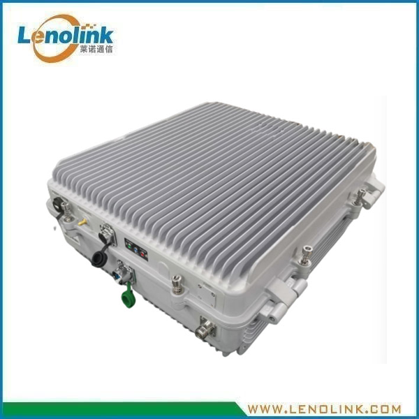
Triple-Band Fiber Optical Digital Repeater Remote Unit (RU)
Product Model: LCVB40A
Applications
Triple-Band Fiber-Optic Distributed Coverage
The Lenolink LCVB40A Triple-Band Fiber Optical Digital Repeater Remote Unit (RU) is designed for multi-band cellular fiber-optic distributed coverage systems.
The RU is designed to work with the corresponding Master Unit (MU) and extend cellular RF coverage to remote locations through a single-mode optical fiber link.
The specified system supports:
- UMTS900
- LTE1800
- LTE2100
Typical applications include:
- Indoor cellular coverage systems
- Large buildings and commercial facilities
- Railway and metro communication systems
- Airports and transportation hubs
- Industrial facilities
- Campus and large-area facilities
- Tunnels and underground facilities
- RF shadow areas
- Cellular coverage blind spots
- Multi-band cellular distributed antenna systems
- Fiber-fed cellular coverage networks
Product Summary
The Lenolink LCVB40A Triple-Band Fiber Optical Digital Repeater Remote Unit (RU) is designed to provide remote cellular RF coverage in a fiber-optic distributed coverage system.
The RU works with the corresponding LCVI30E12 Master Unit (MU) and supports the same three cellular frequency bands:
UMTS900
- Uplink: 880–915 MHz
- Downlink: 925–960 MHz
- Working bandwidth: 35 MHz uplink / 35 MHz downlink
LTE1800
- Uplink: 1710–1785 MHz
- Downlink: 1805–1880 MHz
- Working bandwidth: 75 MHz uplink / 75 MHz downlink
LTE2100
- Uplink: 1920–1980 MHz
- Downlink: 2110–2170 MHz
- Working bandwidth: 60 MHz uplink / 60 MHz downlink
The LCVB40A provides a specified composite downlink RF output power of 40 ± 2 dBm per band and a RU gain of 45 ± 3 dB per band.
A 0–25 dB gain adjustment range and ≥10 dB AGC range provide flexibility for RF level adjustment during system installation and commissioning.
The RU uses single-mode optical fiber with a 1 × LC/UPC optical interface and an optical output power of 0 ± 3 dBm @ 1310 nm.
The enclosure is specified for Indoor & Outdoor (IP65) applications and uses a wall-mounted installation configuration.
Typical System Configuration
The LCVB40A is installed at the remote coverage location and operates together with the central Master Unit.
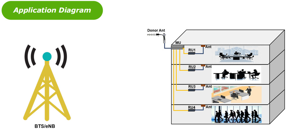
BTS/eNB / Donor Antenna → MU → Optical Fiber → LCVB40A RU → Antenna → Coverage Area
The MU receives the cellular RF signal from the base-station or donor side and converts the signal for optical transmission.
The signal is transmitted through single-mode optical fiber to the LCVB40A Remote Unit.
The RU converts the optical signal back into RF, amplifies the RF signal and provides RF output to the local antenna system.
The uplink signal travels in the reverse direction:
Coverage Area → Antenna → RU → Optical Fiber → MU → BTS/eNB
This architecture allows centralized cellular equipment to provide RF coverage in remote areas through fiber-optic distribution.
Key Specifications
| Parameter | Specification |
|---|---|
| Product Type | Triple-Band Fiber Optical Digital Repeater – Remote Unit (RU) |
| System Bands | UMTS900 / LTE1800 / LTE2100 |
| UMTS900 Uplink | 880–915 MHz |
| UMTS900 Downlink | 925–960 MHz |
| LTE1800 Uplink | 1710–1785 MHz |
| LTE1800 Downlink | 1805–1880 MHz |
| LTE2100 Uplink | 1920–1980 MHz |
| LTE2100 Downlink | 2110–2170 MHz |
| UMTS900 Working Bandwidth | 35 MHz Uplink / 35 MHz Downlink |
| LTE1800 Working Bandwidth | 75 MHz Uplink / 75 MHz Downlink |
| LTE2100 Working Bandwidth | 60 MHz Uplink / 60 MHz Downlink |
| DL RF Output Power | 40 ± 2 dBm per band |
| Gain of RU | 45 ± 3 dB per band |
| Gain Adjustment Range | 0–25 dB |
| AGC | ≥10 dB |
| Maximum Input Power (Non-Destructive) | 10 dBm |
| VSWR | ≤1.5 |
| Spurious Emission | 9 kHz–1 GHz: ≤−36 dBm |
| Spurious Emission | 1 GHz–12.75 GHz: ≤−30 dBm |
| System Delay | ≤1.5 μs |
| I/O Impedance | 50 Ω |
| Fiber Connector | 1 × LC/UPC |
| RF Connector | 1 × N-Female |
| Optical Output Power | 0 ± 3 dBm @ 1310 nm |
| Fiber Type | Single Mode |
| Optical Receiver Sensitivity | ≥−12 dBm |
| Power Supply | AC 220 V, 50/60 Hz |
| Power Consumption | ≤240 W |
| Temperature Range | −20°C to +50°C |
| Humidity | ≤95%, Non-Condensing |
| Application | Indoor & Outdoor (IP65) |
| Dimensions | 500 × 440 × 187 mm |
| Weight | ≤35 kg |
| Mounting | Wall Mounted |
| Local Control | Via USB Interface |
| NMS Mode | Through MU via Fiber Optical Cable |
Note: Product specifications are based on the current engineering configuration and may be customized according to project requirements.
Key Features
- Triple-band cellular operation
- UMTS900 / LTE1800 / LTE2100 support
- Frequency configuration matched with the corresponding MU
- 35 MHz UMTS900 working bandwidth
- 75 MHz LTE1800 working bandwidth
- 60 MHz LTE2100 working bandwidth
- 40 ± 2 dBm composite downlink RF output power per band
- 45 ± 3 dB RU gain per band
- 0–25 dB gain adjustment range
- AGC range ≥10 dB
- VSWR ≤1.5
- System delay ≤1.5 μs
- Single-mode optical fiber transmission
- 1 × LC/UPC optical interface
- 1 × N-Female RF interface
- Optical output power 0 ± 3 dBm @ 1310 nm
- Optical receiver sensitivity ≥−12 dBm
- IP65 indoor and outdoor application
- Wall-mounted design
- USB local control
- NMS through MU via fiber-optic cable
Technical Advantages
Triple-Band Cellular Coverage
The LCVB40A supports three cellular frequency bands within one remote unit: UMTS900 + LTE1800 + LTE2100
This allows multiple cellular services to be distributed through a common fiber-optic coverage architecture.
The three-band configuration makes the RU suitable for multi-band cellular coverage projects where several frequency bands need to be delivered to the same remote area.
Matched MU + RU Architecture
The LCVB40A is designed to work with the corresponding LCVI30E12 Multi-Band Fiber Optical Digital Repeater Master Unit.
The MU and RU use the same cellular frequency configuration:
| System | Uplink | Downlink |
|---|---|---|
| UMTS900 | 880–915 MHz | 925–960 MHz |
| LTE1800 | 1710–1785 MHz | 1805–1880 MHz |
| LTE2100 | 1920–1980 MHz | 2110–2170 MHz |
This provides a clear system-level architecture for multi-band fiber DAS deployment.
High RF Output Power
The specified composite downlink RF output power is: 40 ± 2 dBm per band.
This allows the RU to provide a relatively high RF output level for remote cellular coverage applications.
Actual coverage depends on:
- Antenna gain
- Feeder loss
- Building structure
- Installation environment
- Antenna configuration
- RF distribution design
- System configuration
Flexible Gain Adjustment
The RU provides: 0–25 dB Gain Adjustment Range.
This allows RF levels to be adjusted according to the actual system configuration during installation and commissioning.
The RU also provides: AGC ≥10 dB to support automatic RF level management within the specified operating range.
Low System Delay
The specified system delay is: ≤1.5 μs.
Low system delay is important for distributed cellular RF systems where the RF signal must travel between the central equipment and remote coverage locations.
Single-Mode Fiber Interface
The LCVB40A uses:
- Single-mode fiber
- 1 × LC/UPC optical connector
- 1310 nm optical wavelength
- Optical output power: 0 ± 3 dBm
- Optical receiver sensitivity: ≥−12 dBm
The optical interface connects the RU to the central MU through the fiber-optic distribution network.
IP65 Indoor & Outdoor Design
The LCVB40A is specified for: Indoor & Outdoor — IP65.
The wall-mounted enclosure is designed for remote installation environments where protection against dust and water ingress is required.
Working Principle
How Does a Triple-Band Fiber Optical Remote Unit Work?
The LCVB40A is the remote RF unit in the fiber-optic distributed cellular coverage system.
The basic system architecture is:
BTS/eNB / Donor Antenna → MU → Optical Fiber → RU → Antenna
The RU receives the optical signal from the MU and converts it back into RF.
The RF signal is then amplified and delivered to the local antenna system.
Downlink
The downlink signal follows:
BTS/eNB → MU → Optical Fiber → LCVB40A RU → Antenna → Coverage Area
The MU processes the cellular RF signals and converts them into optical signals.
The optical signal is transmitted through single-mode fiber.
The LCVB40A receives the optical signal and converts it back into RF.
The RU amplifies the RF signal and sends it to the local antenna system.
Uplink
The uplink signal follows the reverse path:
Coverage Area → Antenna → LCVB40A RU → Optical Fiber → MU → BTS/eNB
The RU receives the uplink RF signal from the coverage area.
The signal is converted into an optical signal and transmitted back to the MU.
The MU then interfaces the signal with the base-station side.
MU + RU System Architecture
Complete Multi-Band Fiber DAS System
The Lenolink multi-band fiber-optic distributed coverage system consists primarily of:
Master Unit — LCVI30E12
Located at the central equipment side.
Main functions include:
- RF interface with the base-station side
- Digital RF processing
- RF/optical conversion
- Optical transmission to remote units
- System control
Remote Unit — LCVB40A
Located at the remote coverage location.
Main functions include:
- Optical/RF conversion
- RF amplification
- RF output to the antenna
- Uplink RF reception
- Uplink optical transmission
- Local USB control
- NMS through the MU
System Flow
BTS/eNB / Donor Antenna → LCVI30E12 MU → Fiber Optical Cable → LCVB40A RU → Antenna → Coverage Area
This architecture allows a centralized base-station source to provide cellular coverage across multiple remote areas.
Why Choose Lenolink LCVB40A?
Triple-Band System Integration
The LCVB40A supports: UMTS900 + LTE1800 + LTE2100 in one remote-unit platform.
This simplifies the deployment of multi-band cellular coverage systems.
High-Power Remote Coverage
With: 40 ± 2 dBm composite downlink RF output power per band.
The LCVB40A is designed for remote coverage applications requiring relatively high RF output power.
Flexible RF Level Management
The combination of: 0–25 dB Gain Adjustment and: ≥10 dB AGC, provides flexibility during RF system commissioning and optimization.
Fiber-Optic Distributed Architecture
The RU connects to the central MU through single-mode optical fiber.
This allows remote coverage equipment to be installed away from the central base-station location.
Typical applications include:
- Buildings
- Railway facilities
- Metro systems
- Airports
- Industrial facilities
- Tunnels
- Underground areas
- Campus environments
- Transportation infrastructure
Outdoor-Ready IP65 Design
The IP65 enclosure and wall-mounted configuration allow the RU to be deployed in suitable indoor and outdoor locations.
Centralized NMS Architecture
The specification identifies: NMS Mode: Through MU via Fiber Optical Cable
This means the RU can be incorporated into a centralized MU/RU management architecture rather than requiring an independent management system at each remote location.
RU vs. MU
| Item | LCVI30E12 MU | LCVB40A RU |
|---|---|---|
| System Position | Central equipment side | Remote coverage side |
| System Bands | UMTS900 / LTE1800 / LTE2100 | UMTS900 / LTE1800 / LTE2100 |
| Main Function | RF/digital processing and optical interface | Optical/RF conversion and amplification |
| Fiber Type | Single Mode | Single Mode |
| Optical Connector | 4 × LC/UPC | 1 × LC/UPC |
| RF Connector | 1 × N-Female | 1 × N-Female |
| Gain | 45 ± 3 dB per band | 45 ± 3 dB per band |
| Gain Adjustment | 0–31 dB per sub-band | 0–25 dB |
| System Delay | ≤5 μs | ≤1.5 μs |
| Optical Wavelength | 1550 nm | 1310 nm |
| Installation | Wall Mounted | Wall Mounted |
| Application | Indoor & Outdoor, IP65 | Indoor & Outdoor, IP65 |
| Local Control | USB Interface | USB Interface |
| NMS | Central MU | Through MU via Fiber Optical Cable |
Simple Relationship
MU = Central RF / Digital / Optical Unit
RU = Remote Optical / RF Coverage Unit
This distinction makes it easier for customers to understand which unit is required for a fiber-optic cellular coverage project.
Frequently Asked Questions
Q1: What is the LCVB40A?
The LCVB40A is a Triple-Band Fiber Optical Digital Repeater Remote Unit (RU) designed for fiber-optic distributed cellular coverage systems.
Q2: Which frequency bands does the LCVB40A support?
The specified configuration supports:
UMTS900
880–915 MHz uplink / 925–960 MHz downlink
LTE1800
1710–1785 MHz uplink / 1805–1880 MHz downlink
LTE2100
1920–1980 MHz uplink / 2110–2170 MHz downlink
Q3: Does the RU use the same frequency configuration as the MU?
Yes.
The LCVB40A is designed to work with the corresponding MU using the same:
- UMTS900 configuration
- LTE1800 configuration
- LTE2100 configuration
Q4: What is the working bandwidth?
The specified working bandwidth is:
- UMTS900: 35 MHz uplink / 35 MHz downlink
- LTE1800: 75 MHz uplink / 75 MHz downlink
- LTE2100: 60 MHz uplink / 60 MHz downlink
Q5: What is the RF output power?
The specified composite downlink RF output power is: 40 ± 2 dBm per band
Q6: What is the gain of the RU?
The specified RU gain is: 45 ± 3 dB per band
Q7: Can the RU gain be adjusted?
Yes. The specified gain adjustment range is: 0–25 dB.
Q8: Does the RU support AGC?
Yes. The specified AGC range is: ≥10 dB.
Q9: What type of optical fiber does the RU use?
The LCVB40A uses: Single-mode optical fiber
Q10: What optical connector does the RU use?
The specified optical connector is: 1 × LC/UPC.
Q11: What is the optical output power?
The specified optical output power is: 0 ± 3 dBm @ 1310 nm.
Q12: What is the optical receiver sensitivity?
The supplied technical specification lists: ≥−12 dBm.
This value should be confirmed against the final engineering specification or test report before final publication.
Q13: Can the LCVB40A be installed outdoors?
Yes. The supplied specification identifies the application as: Indoor & Outdoor (IP65)
Actual installation should follow the applicable environmental and mounting requirements.
Q14: What is the system delay?
The specified system delay is: ≤1.5 μs
Q15: What is the power consumption?
The specified power consumption is: ≤240 W
Q16: What is the operating temperature?
The specified temperature range is: −20°C to +50°C
Q17: What is the mounting method?
The LCVB40A uses: Wall Mounting
Dimensions: 500 × 440 × 187 mm
Weight: ≤35 kg
Q18: How is the RU connected to the MU?
The RU is connected to the MU through a: Single-mode optical fiber link
The system architecture is: MU → Optical Fiber → RU
Q19: How is the RU monitored?
The supplied specification identifies: NMS Mode: Through MU via Fiber Optical Cable
Local control is provided through: USB Interface
Q20: Can Lenolink customize the RU?
Yes. Lenolink can evaluate project-specific requirements including:
- Frequency configuration
- Uplink/downlink frequency
- Working bandwidth
- RF output power
- Gain
- Gain adjustment
- Optical interface
- Fiber type
- Optical wavelength
- RF connector
- Mechanical enclosure
- Installation method
- Environmental requirements
- MU/RU system configuration
Request a Customized Multi-Band Fiber DAS Solution
Need a Triple-Band Fiber Optical Repeater for Your Coverage Project?
Please provide:
✓ Required cellular frequency bands
✓ Uplink and downlink frequencies
✓ Required working bandwidth
✓ Number of Remote Units
✓ Required RF output power
✓ Required RU gain
✓ Gain adjustment requirements
✓ Required fiber transmission distance
✓ Optical fiber type
✓ Optical connector type
✓ Coverage area
✓ Antenna configuration
✓ Indoor or outdoor installation
✓ Mounting requirements
✓ Environmental conditions
Lenolink RF engineers can evaluate the project requirements and provide a customized Multi-Band Fiber Optical Digital Repeater Solution.
Contact: info@lenolink.com