

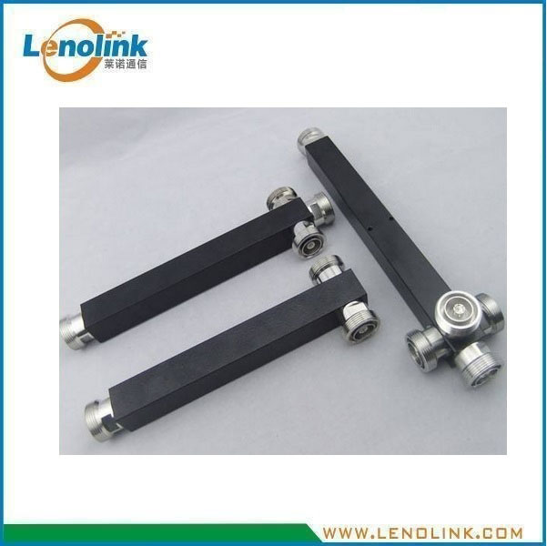
350–3800 MHz Wideband RF Power Splitter
Model:
2-Way, 3-Way and 4-Way Low-PIM Power Splitter for DAS and RF Distribution
Product Summary
Lenolink 350–3800 MHz Wideband RF Power Splitter is designed for dividing RF signals into multiple output paths in DAS, cellular coverage and wireless communication systems.
Available in 2-way, 3-way and 4-way configurations, the splitter supports a wide frequency range from 350 to 3800 MHz, with up to 300 W power handling and specified PIM performance of ≤−150 dBc @ 2 × 43 dBm.
With an IP65-rated enclosure, the RF power splitter is suitable for indoor and appropriate outdoor RF distribution applications. N-Female and 4.3-10 Female connector configurations are available according to project requirements.
Key Specifications
| Parameter | Specification |
|---|---|
| Frequency Range | 350–3800 MHz |
| Configuration | 2-Way / 3-Way / 4-Way |
| Insertion Loss | ≤3.3 dB / ≤5.3 dB / ≤6.6 dB |
| PIM | ≤−150 dBc @ 2 × 43 dBm |
| Power Handling | 300 W |
| Impedance | 50 Ω |
| Operating Temperature | −35°C to +75°C |
| Relative Humidity | ≤95% |
| Application | Indoor / Outdoor |
| Waterproof Grade | IP65 |
| RF Connector | N-Female / 4.3-10 Female, configurable |
| Housing Color | Black or Custom |
2-Way, 3-Way and 4-Way Configurations
Lenolink provides multiple RF power splitter configurations to meet different RF distribution requirements.
| Specification | 2-Way | 3-Way | 4-Way |
|---|---|---|---|
| Frequency Range | 350–3800 MHz | 350–3800 MHz | 350–3800 MHz |
| Number of Outputs | 2 | 3 | 4 |
| Insertion Loss | ≤3.3 dB | ≤5.3 dB | ≤6.6 dB |
| VSWR | ≤1.35 @ 350–380 MHz; ≤1.25 @ 380–3800 MHz | ≤1.30 | ≤1.35 |
| PIM | ≤−150 dBc @ 2 × 43 dBm | ≤−150 dBc @ 2 × 43 dBm | ≤−150 dBc @ 2 × 43 dBm |
| Power Handling | 300 W | 300 W | 300 W |
| Impedance | 50 Ω | 50 Ω | 50 Ω |
The appropriate splitter configuration can be selected according to the required number of RF output branches and the overall distribution architecture.
VSWR Specifications
The VSWR performance varies according to the splitter configuration and frequency range.
| Configuration | VSWR |
|---|---|
| 2-Way | ≤1.35 @ 350–380 MHz; ≤1.25 @ 380–3800 MHz |
| 3-Way | ≤1.30 |
| 4-Way | ≤1.35 |
Environmental Specifications
| Parameter | Specification |
|---|---|
| Operating Temperature | −35°C to +75°C |
| Relative Humidity | ≤95% |
| Application | Indoor / Outdoor |
| Waterproof Grade | IP65 |
The product is designed for indoor and suitable outdoor RF distribution environments within the specified operating conditions.
Environmental Specifications
| Parameter | Specification |
|---|---|
| Operating Temperature | −35°C to +75°C |
| Relative Humidity | ≤95% |
| Application | Indoor / Outdoor |
| Waterproof Grade | IP65 |
The product is designed for indoor and suitable outdoor RF distribution environments within the specified operating conditions.
Mechanical Specifications
| Parameter | Specification |
|---|---|
| RF Connector | N-Female / 4.3-10 Female, configurable |
| Housing Color | Black or Custom |
| Environmental Protection | IP65 |
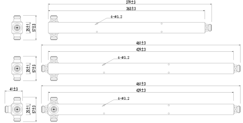
| Mechanical Configuration | See Mechanical Drawing |
Mechanical Drawing (Unit: mm)
The mechanical dimensions vary according to the splitter configuration. Please refer to the corresponding mechanical drawing for detailed dimensions.
Key Features
- 350–3800 MHz wide frequency range
- 2-way, 3-way and 4-way configurations
- Up to 300 W power handling
- PIM ≤−150 dBc @ 2 × 43 dBm
- Controlled VSWR across the specified frequency range
- 50 Ω impedance
- N-Female or 4.3-10 Female connector configurations
- Indoor and outdoor applications
- IP65 environmental protection
- Black or customized housing color
- Suitable for DAS and cellular RF distribution
Technical Advantages
- Wide Frequency Range
The splitter supports a specified frequency range of 350–3800 MHz, making it suitable for a wide range of cellular and wireless RF distribution applications.
- Multiple Splitting Configurations
2-way, 3-way and 4-way configurations provide flexibility when distributing RF signals to different numbers of branches or coverage zones.
- High Power Handling
With a specified power handling capability of 300 W, the splitter can be used in RF distribution systems requiring relatively high RF power capacity.
- Low-PIM Performance
The splitter provides specified PIM performance of ≤−150 dBc @ 2 × 43 dBm, supporting applications where low passive intermodulation performance is important.
- Controlled VSWR
The product provides defined VSWR performance across the specified frequency range, helping maintain suitable RF interface performance within the distribution network.
- IP65 Protection
The IP65-rated enclosure provides environmental protection for suitable indoor and outdoor RF distribution installations.
- Flexible Connector Configuration
The RF splitter can be configured with N-Female or 4.3-10 Female connectors according to application and project requirements.
How Does an RF Power Splitter Work?
An RF power splitter is a passive RF component used to divide an incoming RF signal into multiple output paths.
For example, a 2-way splitter divides one RF input into two output paths, while 3-way and 4-way versions provide three and four output paths respectively.
Typical RF Signal Distribution
RF Input
↓
RF Power Splitter
↓
Multiple RF Output Paths
↓
DAS / RF Distribution Network
↓
Antennas
The power splitter does not amplify the RF signal. Instead, it passively distributes the input RF signal among multiple output ports. The resulting insertion loss depends on the splitter configuration.
RF Power Splitter in a DAS System
An RF power splitter is commonly used as part of a distributed RF network to divide RF signals between multiple antenna branches.
Typical DAS RF Architecture
BTS / Repeater
↓
POI / RF Combiner
↓
RF Distribution Network
↓
Power Splitter
↓
Multiple RF Branches
↓
DAS Antennas
For larger or more complex systems, power splitters can be combined with POIs, RF combiners, filters, couplers, tappers, cables and DAS antennas to create the required RF distribution architecture.
The final configuration should be determined according to RF power levels, frequency bands, distribution losses, number of branches and system requirements.
Typical Applications
- DAS RF Distribution
The power splitter can be used to distribute RF signals to multiple branches within a distributed antenna system.
- Cellular Coverage Systems
Suitable for RF distribution in cellular coverage systems supporting applicable frequency bands within the specified range.
- Multi-Band Wireless Networks
The wide frequency range allows the splitter to be integrated into RF distribution systems covering multiple wireless frequency bands.
- Indoor RF Distribution
Typical indoor applications include:
- Commercial Buildings
- Office Buildings
- Hotels
- Shopping Centers
- Public Buildings
- Enterprise Facilities
- Transportation Facilities
- Outdoor RF Distribution
The IP65 enclosure supports suitable outdoor RF distribution installations where environmental conditions meet the product requirements.
Why Choose Lenolink RF Power Splitters?
- RF Product Expertise
Lenolink provides RF passive components for cellular coverage, DAS and wireless communication applications.
- Multiple RF Configurations
2-way, 3-way and 4-way configurations provide flexibility for different RF distribution architectures.
- Low-PIM Options
Specified low-PIM performance supports RF infrastructure where passive intermodulation performance is an important consideration.
- High-Power Capability
Up to 300 W power handling provides a suitable option for RF distribution systems requiring relatively high power capacity.
- Flexible Connector Configuration
N-Female and 4.3-10 Female configurations are available according to application and project requirements.
- System-Level Integration
The RF power splitter can be integrated with Lenolink POIs, combiners, filters, couplers, tappers and DAS antennas as part of a complete RF distribution system.
- Manufacturer Technical Support
Lenolink provides technical support for product selection, RF configuration and project-specific requirements.
Frequently Asked Questions
- What frequency range does the Lenolink RF power splitter support?
The RF power splitter is specified for 350–3800 MHz operation.
2. What configurations are available?
The product is available in 2-way, 3-way and 4-way configurations.
3. What is the maximum power handling?
The specified power handling is 300 W.
4. What is the PIM performance?
The specified PIM performance is ≤−150 dBc @ 2 × 43 dBm.
5. What is the impedance of the RF splitter?
The RF impedance is 50 Ω.
6. What is the VSWR of the 2-way splitter?
For the 2-way configuration, VSWR is specified as ≤1.35 at 350–380 MHz and ≤1.25 at 380–3800 MHz.
7. Can the RF power splitter be used outdoors?
Yes. The product is specified for indoor/outdoor applications and has an IP65 environmental protection rating. Installation should be carried out according to the applicable environmental and system requirements.
8. What RF connectors are available?
The splitter can be configured with N-Female or 4.3-10 Female connectors according to application and project requirements.
9. Can the housing color be customized?
The standard housing color is black, and custom color options are available according to project requirements.
10. Where is an RF power splitter typically used?
Typical applications include DAS, cellular coverage systems, wireless RF distribution networks, commercial buildings, transportation facilities and other RF infrastructure applications.
Need a Wideband RF Power Splitter?
Lenolink provides 350–3800 MHz RF power splitters in 2-way, 3-way and 4-way configurations for DAS, cellular coverage and RF distribution applications.
Send us your:
- Frequency Band
- RF Power
- Number of Outputs
- Connector Requirement
Our RF engineering team can review your requirements and help determine a suitable RF power splitter configuration.
Contact: info@lenolink.com