

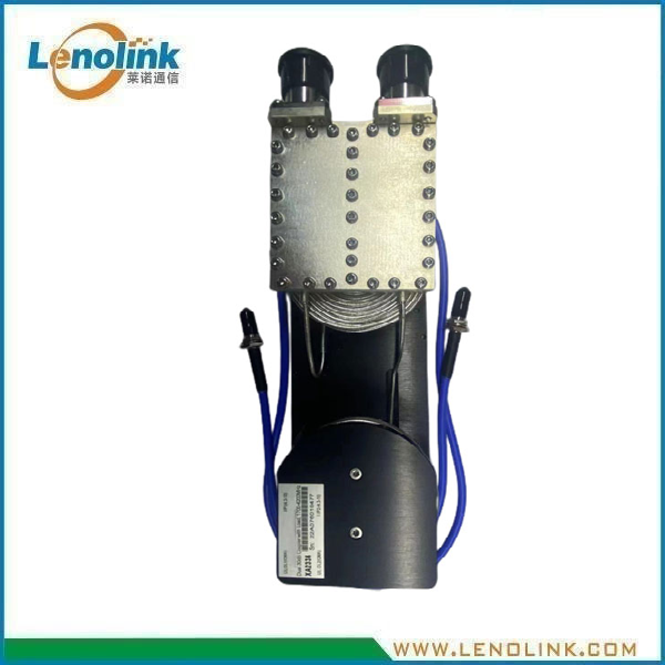
1.7–4.2 GHz Dual 30 dB RF Coupler with Loads
High-Isolation RF Coupling Assembly for 5G and Wireless Infrastructure
Dual 30 dB RF Coupler with Integrated Loads
Lenolink G5226E is a dual 30 dB RF coupler assembly designed for RF signal coupling and distribution applications in the 1.7–4.2 GHz frequency range.
The assembly provides a specified coupling value of 30 ± 1.8 dB, together with ≥80 dB isolation between the specified input and UL/DL paths.
The product uses a 50 Ω RF interface and features 4.3-10 Female input connectors, QMA Female UL/DL ports and SMA interfaces for the internal coupling configuration.
With specified PIM performance of ≤−160 dBc @ 2 × 43 dBm, the G5226E is designed for RF infrastructure applications where controlled signal coupling, high isolation and low passive intermodulation are required.
Dual RF Coupling Configuration
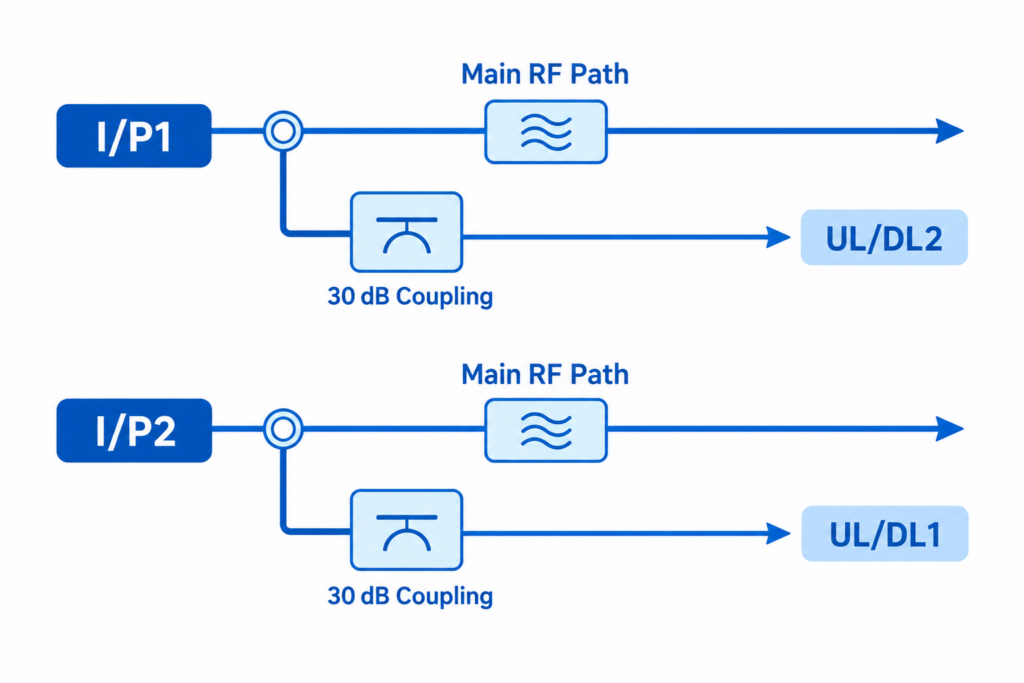
The G5226E incorporates two coupling paths within a single RF assembly.
According to the supplied specification:
- I/P1 → UL/DL2: 30 ± 1.8 dB coupling
- I/P2 → UL/DL1: 30 ± 1.8 dB coupling
- Specified isolation between the corresponding paths: ≥80 dB
This dual-path configuration provides controlled RF coupling while maintaining high isolation between the specified RF paths.
Key Specifications
| Parameter | Specification |
|---|---|
| Model | G5226E |
| Frequency Range | 1.7–4.2 GHz |
| Coupling | 30 ± 1.8 dB |
| Return Loss | ≥15.4 dB |
| Isolation | ≥80 dB |
| Impedance | 50 Ω |
| PIM, 3rd Order | ≤−160 dBc @ 2 × 43 dBm |
| Input Power, CW | 10 W per input |
| Input Power, CW Limited Time | 40 W per input |
| Input Power, Peak | 400 W per input |
| Input Connector | 4.3-10 Female |
| UL/DL Port Connector | QMA Female |
| C/P Connector | SMA |
| Main Coupler Output | RG405 Cable Flange |
| Operating Temperature | Not specified in supplied document |
| Dimensions | Per mechanical drawing |
| Weight | Not specified |
| Load Configuration | Integrated loads, per product configuration |
Maximum Composite Input Power
| Input Power Condition | Maximum Input Power |
|---|---|
| CW | 10 W per input |
| CW, Limited Time | 40 W per input |
| Peak | 400 W per input |
Note: The specified input power limits depend on the operating condition. The 400 W value is specified as peak input power and should not be interpreted as continuous CW power.
High Isolation Between RF Paths
The G5226E provides specified isolation of ≥80 dB between the following RF paths:
- I/P1 → UL/DL2
- I/P2 → UL/DL1
The high isolation specification helps limit unwanted RF coupling between the designated signal paths.
Ultra-Low PIM Performance
The G5226E provides specified third-order passive intermodulation performance of:
≤−160 dBc @ 2 × 43 dBm
This low-PIM specification makes the assembly suitable for RF infrastructure where passive intermodulation performance is an important system consideration.
Working Principle
How Does the Dual RF Coupler Work?
The G5226E uses two RF coupling paths to sample a controlled portion of the RF signal from the designated input paths.
The coupling value is specified at 30 ± 1.8 dB, while the main RF paths maintain the required RF transmission characteristics.
The dual configuration provides coupling between the specified input and UL/DL paths while maintaining ≥80 dB isolation between the corresponding paths.
The integrated load configuration provides the required RF termination within the assembly.
Simplified RF Configuration
Mechanical Specifications
Mechanical Specifications
| Parameter | Specification |
|---|---|
| Dimensions | Per mechanical drawing |
| Input Connector | 4.3-10 Female |
| UL/DL Port | QMA Female |
| C/P | SMA |
| Main Coupler Output | RG405 Cable Flange |
| Load Configuration | Integrated loads |
| Housing / Finish | According to product configuration |
Typical Applications
RF Distribution Systems
The G5226E can be integrated into RF distribution architectures requiring controlled RF signal coupling and high isolation.
Cellular and Wireless Infrastructure
The 1.7–4.2 GHz operating range makes the assembly suitable for applicable cellular and wireless communication infrastructure.
Multi-Path RF Systems
The dual coupling configuration can be used in systems requiring two controlled RF coupling paths within a compact assembly.
RF Monitoring and Signal Sampling
The coupled RF paths can be used where controlled RF sampling is required for system monitoring, measurement or distribution.
RF Equipment Integration
The multi-interface connector configuration allows the assembly to be integrated into specialized RF equipment and distribution architectures.
Key Features
- 1.7–4.2 GHz operating frequency
- Dual 30 dB RF coupling configuration
- 30 ± 1.8 dB coupling
- ≥80 dB specified isolation
- ≥15.4 dB return loss
- ≤−160 dBc PIM @ 2 × 43 dBm
- 50 Ω impedance
- 10 W CW input power per input
- 40 W CW limited-time input per input
- 400 W peak input power per input
- 4.3-10 Female input connectors
- QMA Female UL/DL interfaces
- SMA C/P interface
- Integrated load configuration
- Compact RF assembly
Technical Advantages
Dual Coupling Architecture
Two coupling paths are integrated into a single RF assembly, simplifying integration where dual RF coupling is required.
30 dB Coupling
The specified coupling value of 30 ± 1.8 dB provides controlled RF signal sampling.
High Isolation
The specified isolation of ≥80 dB provides strong separation between the designated RF paths.
Low-PIM Performance
With PIM specified at ≤−160 dBc @ 2 × 43 dBm, the assembly supports RF applications where passive intermodulation performance is important.
Wide Frequency Range
The 1.7–4.2 GHz frequency range covers a broad portion of modern cellular and wireless RF applications.
Multiple RF Interfaces
The combination of 4.3-10 Female, QMA Female, SMA and RG405 cable flange interfaces provides a configuration suitable for specialized RF equipment integration.
Frequently Asked Questions
What frequency range does the G5226E support?
The G5226E is specified for 1.7–4.2 GHz operation.
What is the coupling value?
The specified coupling is 30 ± 1.8 dB.
Is this a single or dual RF coupler?
The product is specified as a Dual 30 dB Coupler with Loads, with two designated RF coupling paths.
What is the isolation?
The specified isolation is ≥80 dB between the corresponding RF paths.
What is the return loss?
The specified return loss is ≥15.4 dB.
What is the PIM performance?
The specified third-order PIM performance is ≤−160 dBc @ 2 × 43 dBm.
What is the maximum input power?
The specified maximum composite input power at each input is:
- 10 W CW
- 40 W CW, limited time
- 400 W peak
The 400 W value is a peak specification and should not be treated as continuous CW power.
What is the impedance?
The RF impedance is 50 Ω.
What connectors are used?
The specified configuration includes:
- 4.3-10 Female input connectors
- QMA Female UL/DL ports
- SMA C/P connector
- RG405 cable flange for the main coupler output
Does the product include RF loads?
Yes. The product is specified as a Dual 30 dB Coupler with Loads, with integrated load components according to the supplied configuration.
What applications is this RF coupler designed for?
The product is intended for specialized RF distribution, signal coupling and wireless communication infrastructure applications within the specified 1.7–4.2 GHz frequency range.
Need a Customized RF Coupling Assembly?
Lenolink provides RF coupling components and assemblies for cellular, DAS and wireless communication infrastructure.
If you require a specific:
- Frequency Range
- Coupling Value
- Isolation
- RF Power
- Connector Configuration
send your requirements to our RF engineering team.
Contact: info@lenolink.com