

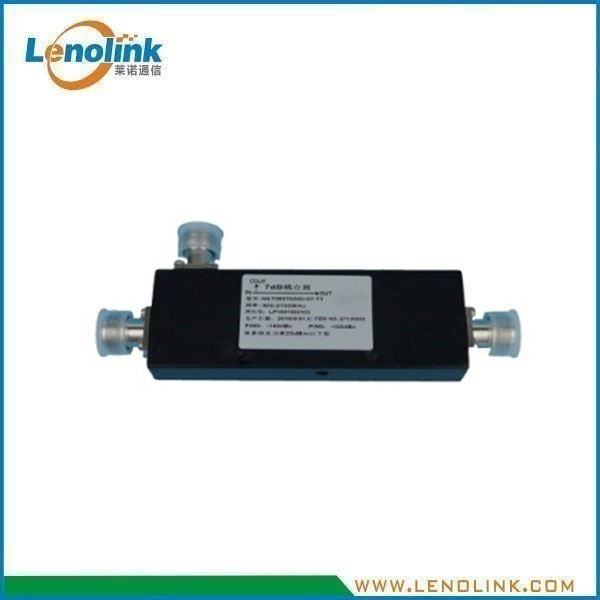
350–3800 MHz Wideband RF Directional Coupler
5–30 dB Coupling Options for DAS and RF Distribution Systems
Products Summary
Lenolink 350–3800 MHz Wideband RF Directional Coupler is designed for controlled RF signal coupling in distributed antenna systems, cellular coverage systems and other RF distribution networks.
The coupler is available with multiple coupling values from 5 dB to 30 dB, including 5, 6, 7, 8, 10, 13, 15, 20 and 30 dB options.
With a specified frequency range of 350–3800 MHz, up to 300 W power handling, ≤−150 dBc PIM performance and IP65 environmental protection, the coupler is suitable for RF distribution applications requiring controlled signal sampling or coupling.
The product uses a 50 Ω RF interface and is equipped with N-Female connectors according to the supplied specification.
Key Specifications
| Parameter | Specification |
|---|---|
| Frequency Range | 350–3800 MHz |
| Coupling Options | 5 / 6 / 7 / 8 / 10 / 13 / 15 / 20 / 30 dB |
| Coupling Tolerance | See configuration table |
| Insertion Loss | ≤2.3 to ≤0.3 dB, depending on coupling value |
| Isolation | ≥23 to ≥45 dB, depending on coupling value |
| VSWR | ≤1.30 |
| PIM | ≤−150 dBc @ 2 × 43 dBm |
| Power Handling | 300 W |
| Impedance | 50 Ω |
| RF Connector | N-Female |
| Operating Temperature | −35°C to +75°C |
| Relative Humidity | ≤95% |
| Application | Indoor / Outdoor |
| Waterproof Grade | IP65 |
| Weight | 510 g |
| Color | Black or Custom |
Electrical Specifications
| Coupling Value | 5 dB | 6 dB | 7 dB | 8 dB | 10 dB | 13 dB | 15 dB | 20 dB | 30 dB |
|---|---|---|---|---|---|---|---|---|---|
| Coupling Tolerance @ 350–380 MHz | ±1.3 dB | ±1.3 dB | ±1.3 dB | ±1.6 dB | ±1.6 dB | ±1.6 dB | ±1.6 dB | ±1.9 dB | ±2.1 dB |
| Coupling Tolerance @ 380–3800 MHz | ±1.2 dB | ±1.2 dB | ±1.2 dB | ±1.5 dB | ±1.5 dB | ±1.5 dB | ±1.5 dB | ±1.8 dB | ±2.0 dB |
| Insertion Loss | ≤2.3 dB | ≤1.76 dB | ≤1.47 dB | ≤1.27 dB | ≤0.96 dB | ≤0.60 dB | ≤0.44 dB | ≤0.34 dB | ≤0.30 dB |
| Isolation | ≥23 dB | ≥24 dB | ≥25 dB | ≥26 dB | ≥28 dB | ≥31 dB | ≥30 dB | ≥35 dB |
Note: Coupling tolerance, insertion loss and isolation vary according to the selected coupling configuration.
Key Features
- 350–3800 MHz wide frequency range
- Nine coupling options from 5 dB to 30 dB
- 5 / 6 / 7 / 8 / 10 / 13 / 15 / 20 / 30 dB configurations
- Up to 300 W power handling
- PIM ≤−150 dBc @ 2 × 43 dBm
- VSWR ≤1.30
- Specified isolation from ≥23 dB to ≥45 dB
- Low main-line insertion loss
- 50 Ω impedance
- N-Female RF connector
- IP65 environmental protection
- Indoor / outdoor applications
- Black or customized housing color
What Is an RF Directional Coupler?
An RF directional coupler is a passive RF component used to couple or sample a defined portion of an RF signal while maintaining the main RF transmission path.
The coupling value indicates the nominal relationship between the main-line RF signal and the signal available at the coupled port.
Different coupling values can therefore be selected according to the RF system architecture and the required coupled signal level.
For example:
- 5 dB coupling provides a relatively higher coupled signal level.
- 10 dB coupling provides a lower coupled signal level than a 5 dB version.
- 20 dB coupling provides a smaller sampled RF signal.
- 30 dB coupling provides a relatively low coupled signal level.
This makes RF directional couplers useful in RF distribution, DAS, signal sampling and monitoring applications.
How Does an RF Directional Coupler Work?
An RF directional coupler uses a passive coupling structure to transfer a controlled portion of RF energy from the main transmission path to a coupled port.
A typical signal path can be represented as:
RF Input
↓
RF Directional Coupler
↓
Main RF Output
and
Coupled RF Signal
↓
Monitoring / Distribution / RF Branch
The main RF signal continues through the primary transmission path, while a controlled portion of the signal is available through the coupled port.
The coupling value determines how much RF signal is sampled.
The RF coupler does not amplify the signal. It is a passive RF component used for controlled RF signal coupling and distribution.
RF Directional Coupler in a DAS System
RF directional couplers can be integrated into distributed antenna systems to provide controlled RF signal coupling within the distribution network.
Typical DAS Architecture
BTS / Repeater
↓
POI / RF Combiner
↓
RF Distribution Network
↓
Directional Coupler
↓
RF Branch / Monitoring Point
↓
Splitter / Coupler
↓
DAS Antennas
Depending on the system architecture, the coupler can work together with other passive RF components such as POIs, RF combiners, filters, power splitters, tappers, coaxial cables and DAS antennas.
The final configuration should be determined according to frequency bands, RF power levels, required coupling value, distribution losses and system requirements.
Directional Coupler vs. RF Power Splitter
Although directional couplers and power splitters are both passive RF components, they serve different functions within an RF distribution system.
| Feature | RF Directional Coupler | RF Power Splitter |
|---|---|---|
| Main Function | Couples a defined portion of an RF signal | Divides RF signal into multiple output paths |
| Typical Configuration | Main RF path + coupled port | One input + multiple outputs |
| Coupling Options | 5 / 6 / 7 / 8 / 10 / 13 / 15 / 20 / 30 dB | 2-Way / 3-Way / 4-Way |
| Typical Application | Signal sampling and controlled coupling | RF signal distribution |
| DAS Application | Coupling / monitoring / distribution | Branch distribution |
This distinction helps system integrators select the appropriate passive RF component for each part of the RF architecture.
Environmental Specifications
| Parameter | Specification |
|---|---|
| Operating Temperature | −35°C to +75°C |
| Relative Humidity | ≤95% |
| Application | Indoor / Outdoor |
| Waterproof Grade | IP65 |
The RF coupler is designed for operation within the specified environmental conditions.
Mechanical Specifications
| Parameter | Specification |
|---|---|
| Main Dimensions | Approx. 164 × 45 × 23 mm* |
| RF Connector | N-Female |
| Weight | 510 g |
| Housing Color | Black or Custom |
| Environmental Protection | IP65 |
* Please refer to the mechanical drawing for detailed dimensional tolerances and configuration-specific dimensions.
Mechanical Drawing (Unit: mm)
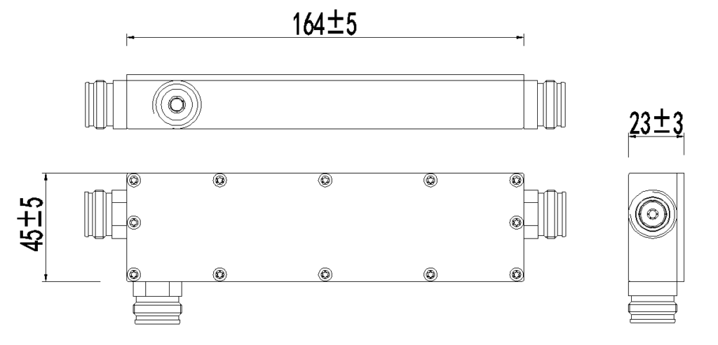
The mechanical drawing provides the main dimensional information for the RF directional coupler.
Technical Advantages
- Wide Frequency Coverage
The RF directional coupler supports a specified frequency range of 350–3800 MHz, allowing it to be used in a wide range of cellular and wireless RF distribution applications.
- Nine Coupling Options
Nine coupling configurations from 5 dB to 30 dB provide flexibility for different signal sampling and RF distribution requirements.
- Controlled RF Coupling
Different coupling values allow system designers to select an appropriate coupled signal level according to the RF architecture.
- Low Main-Line Insertion Loss
The specified insertion loss ranges from ≤2.3 dB to ≤0.3 dB, depending on the selected coupling value.
- High Isolation
Specified isolation ranges from ≥23 dB to ≥45 dB, depending on the selected coupling configuration.
- Low-PIM Performance
The RF coupler provides specified PIM performance of ≤−150 dBc @ 2 × 43 dBm, supporting RF infrastructure where passive intermodulation performance is important.
- High Power Handling
The coupler supports up to 300 W power handling according to the supplied specification.
- IP65 Environmental Protection
The IP65-rated enclosure provides environmental protection for suitable indoor and outdoor RF distribution installations.
Typical Applications
- DAS RF Distribution
The RF directional coupler can be integrated into DAS networks to provide controlled RF signal coupling between the main RF path and selected branches.
- Cellular Coverage Systems
The wide frequency range makes the coupler suitable for applicable cellular coverage and RF distribution systems.
- Indoor RF Distribution
Typical indoor applications include:
- Commercial Buildings
- Office Buildings
- Hotels
- Shopping Centers
- Enterprise Facilities
- Public Buildings
- Transportation Facilities
- Outdoor RF Distribution
The IP65 enclosure supports suitable outdoor RF distribution installations where environmental conditions meet the product requirements.
- RF Signal Monitoring
The coupled RF port can provide a controlled RF sample for monitoring or measurement applications where required by the system architecture.
- RF Testing and Commissioning
The coupler can also be used where a controlled RF sampling point is required during system testing, commissioning or maintenance.
Why Choose Lenolink RF Directional Couplers?
- Wideband RF Capability
The 350–3800 MHz frequency range supports a wide range of cellular and wireless RF distribution applications.
- Multiple Coupling Configurations
Nine coupling options from 5 dB to 30 dB provide flexibility for different RF system requirements.
- Low-PIM Performance
The specified ≤−150 dBc PIM @ 2 × 43 dBm supports applications where passive intermodulation performance is an important consideration.
- High-Power Capability
With up to 300 W power handling, the coupler can be integrated into applicable high-power RF distribution systems.
- Robust Environmental Design
The IP65 enclosure and −35°C to +75°C operating temperature range support suitable indoor and outdoor installations.
- System-Level Integration
The RF directional coupler can be integrated with Lenolink’s RF passive components, including POIs, RF combiners, filters, power splitters, tappers and DAS antennas.
- Technical Support
Lenolink provides technical assistance for RF product selection, configuration and project-specific requirements.
Frequently Asked Questions
1. What frequency range does the RF directional coupler support?
The RF directional coupler supports a specified frequency range of 350–3800 MHz.
2. What coupling values are available?
The available coupling values are: 5, 6, 7, 8, 10, 13, 15, 20 and 30 dB.
3. Is the coupling value continuously adjustable?
No. The supplied specification defines nine coupling configurations rather than a continuously adjustable coupling range.
4. What is the maximum power handling?
The specified power handling is 300 W.
5. What is the PIM performance?
The specified PIM performance is ≤−150 dBc @ 2 × 43 dBm.
6. What is the VSWR?
The specified VSWR is ≤1.30.
7. What is the impedance?
The RF impedance is 50 Ω.
8.What RF connector is used?
The supplied specification lists N-Female as the RF connector.
9. Can the coupler be used outdoors?
Yes. The product is specified for Indoor/Outdoor applications and has an IP65 waterproof grade.
Installation should comply with the environmental conditions and requirements of the actual application.
10. What is the difference between a coupler and a power splitter?
A directional coupler samples or couples a defined portion of an RF signal from the main transmission path, while a power splitter divides an RF input into multiple output paths.
11. How do I select the coupling value?
The appropriate coupling value depends on the required coupled signal level and the RF distribution architecture. Customers can provide the system frequency, RF power and required signal level, and Lenolink can review the application requirements.
Need a Wideband RF Directional Coupler?
Lenolink provides 350–3800 MHz RF directional couplers with nine coupling configurations from 5 dB to 30 dB, supporting DAS, cellular coverage and RF distribution applications.
Send us your:
- Frequency Band
- RF Power
- Number of Outputs
- Connector Requirement
Our RF engineering team can review your requirements and help determine a suitable RF directional coupler configuration.
Contact: info@lenolink.com