

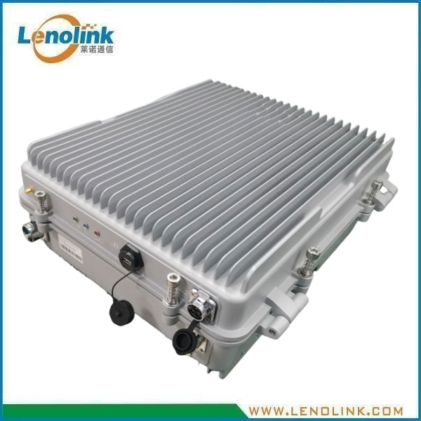
Multi-Band Fiber Optical Digital Repeater Master Unit (MU)
Product Model: LCVI30E12
Applications
Multi-Band Cellular Fiber-Optic Distributed Coverage
The Lenolink Multi-Band Fiber Optical Digital Repeater Master Unit (MU) is designed for fiber-optic distributed coverage systems supporting multiple cellular frequency bands.
According to the specified configuration, the MU supports:
- UMTS 900
- LTE 1800
- LTE 2100
The MU is designed to interface with the base-station RF source and distribute RF signals to remote units through a single-mode optical fiber link.
Typical applications include:
- Indoor cellular coverage systems
- Large buildings and commercial facilities
- Transportation hubs
- Railway and metro facilities
- Airports
- Industrial facilities
- Campus networks
- Underground facilities
- Tunnels and RF shadow areas
- Multi-band wireless coverage systems
- Cellular distributed antenna systems
Product Summary
The Lenolink Multi-Band Fiber Optical Digital Repeater Master Unit (MU) is designed as the central RF-to-optical unit of a fiber-optic distributed cellular coverage system.
The specified configuration supports three cellular frequency bands:
- UMTS 900: 880–915 MHz uplink / 925–960 MHz downlink
- LTE 1800: 1710–1785 MHz uplink / 1805–1880 MHz downlink
- LTE 2100: 1920–1980 MHz uplink / 2110–2170 MHz downlink
The MU supports independent digital filtering for each supported band. The specified configuration provides 4 sub-bands per system band, with each sub-band supporting a variable bandwidth of 1–3 MHz.
Each sub-band can be individually switched ON or OFF through software, providing flexible frequency allocation and system configuration.
The MU provides:
- 27 ± 2 dBm UL RF output power per band
- 45 ± 3 dB gain per band
- 0–31 dB gain adjustment per sub-band
- ≤20 km specified transmission distance
- 4 × LC/UPC optical interfaces
- 1 × N-Female RF interface
- Single-mode fiber transmission
The unit is designed for indoor and outdoor installation with an IP65 application rating and a wall-mounted mechanical configuration.
Typical System Configuration
The MU is installed at the central equipment side of the fiber-optic distributed coverage system.
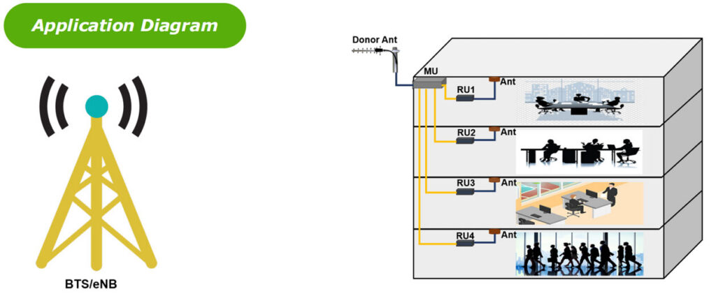
Base Station / BTS → RF → MU → Optical Fiber → Remote Unit → Antenna → Coverage Area
The MU receives RF signals from the cellular base-station side and performs digital filtering and RF/optical conversion.
The processed RF signals are transmitted through a single-mode optical fiber link to remote units.
At the remote location, the remote unit converts the optical signal back to RF and provides RF coverage through the antenna system.
Multi-Band System Architecture
UMTS900 + LTE1800 + LTE2100
The multi-band configuration allows several cellular services to be distributed through a common fiber-optic coverage architecture.
Key Specifications
| Parameter | Specification |
|---|---|
| Product Type | Multi-Band Fiber Optical Digital Repeater – Master Unit (MU) |
| System Bands | UMTS900 / LTE1800 / LTE2100 |
| UMTS900 Uplink | 880–915 MHz |
| UMTS900 Downlink | 925–960 MHz |
| LTE1800 Uplink | 1710–1785 MHz |
| LTE1800 Downlink | 1805–1880 MHz |
| LTE2100 Uplink | 1920–1980 MHz |
| LTE2100 Downlink | 2110–2170 MHz |
| Digital Filter | 4 sub-bands per band |
| Sub-Band Bandwidth | 1–3 MHz variable per sub-band |
| Sub-Band Control | Individually switchable ON/OFF by software |
| UL RF Output Power | 27 ± 2 dBm per band |
| MU Gain | 45 ± 3 dB per band |
| Gain Adjustment Range | 0–31 dB, adjustable for each sub-band |
| Transmission Distance | ≤20 km |
| Maximum Input Power | −10 dBm, non-destructive |
| VSWR | ≤1.5 |
| Spurious Emission | 9 kHz–1 GHz: ≤−36 dBm |
| Spurious Emission | 1 GHz–12.75 GHz: ≤−30 dBm |
| Noise Figure @ 1 RU Connection | ≤8 dB |
| System Delay | ≤5 μs |
| I/O Impedance | 50 Ω |
| RF Connector | 1 × N-Female |
| Fiber Connector | 4 × LC/UPC |
| Fiber Type | Single Mode |
| Optical Output Power | −3 ± 3 dBm @ 1550 nm |
| Optical Receiver Sensitivity | ≥−12 dBm |
| Power Supply | AC 220 V, 50/60 Hz |
| Power Consumption | ≤120 W |
| Temperature Range | −20°C to +50°C |
| Humidity | ≤95%, non-condensing |
| Application | Indoor & Outdoor, IP65 |
| Dimensions | 447 × 357 × 171 mm |
| Weight | ≤16 kg |
| Mounting | Wall Mounted |
| Local Control | Via USB Interface |
Note: Product specifications are based on the current engineering configuration and may be customized according to project requirements.
Key Features
- Triple-band cellular operation
- UMTS900 / LTE1800 / LTE2100 support
- 4 independently configurable sub-bands per system band
- 1–3 MHz variable bandwidth per sub-band
- Individual software ON/OFF control for each sub-band
- 27 ± 2 dBm UL RF output power per band
- 45 ± 3 dB gain per band
- 0–31 dB gain adjustment for each sub-band
- up to 20 km fiber transmission distance
- Single-mode optical fiber transmission
- 4 × LC/UPC optical connectors
- 1 × N-Female RF connector
- Optical output power −3 ± 3 dBm @ 1550 nm
- Optical receiver sensitivity ≥−12 dBm
- VSWR ≤1.5
- System delay ≤5 μs
- IP65 indoor/outdoor application
- Wall-mounted design
- USB local control
- Designed for multi-band cellular distributed coverage systems
Technical Advantages
Multi-Band Cellular Coverage
The MU supports three cellular frequency bands within one distributed coverage platform: UMTS900 + LTE1800 + LTE2100
This allows multiple wireless services to be distributed through a common fiber-optic infrastructure.
Flexible Digital Sub-Band Filtering
One of the main technical features of this MU is its configurable digital filtering architecture.
The specified configuration provides: 4 sub-bands per system band
Each sub-band supports: 1–3 MHz variable bandwidth
Each sub-band can also be individually switched: ON / OFF by software
This provides greater flexibility than a fixed wideband RF repeater when a project requires selective frequency allocation.
Independent Gain Adjustment
The MU provides a gain adjustment range of: 0–31 dB
The gain can be adjusted for each sub-band according to the specified configuration.
This allows system engineers to optimize RF levels during system commissioning and frequency planning.
Multi-Band RF Output
The specified UL RF output power is: 27 ± 2 dBm per band
The MU gain is: 45 ± 3 dB per band
These parameters provide the RF level required for the optical distribution system while maintaining independent control of the supported cellular bands.
Long-Distance Fiber Transmission
The specified transmission distance is: ≤20 km
This allows the MU to support distributed coverage systems where remote units are located considerable distances from the central equipment room.
Actual transmission distance should be evaluated according to optical link budget, fiber type, connector loss, optical output power, receiver sensitivity and system configuration.
Single-Mode Optical Interface
The MU uses:
- Single-mode optical fiber
- 4 × LC/UPC optical connectors
- 1550 nm optical wavelength
- −3 ± 3 dBm optical output power
- ≥−12 dBm optical receiver sensitivity
The multi-port optical interface allows the MU to support distributed remote-unit configurations.
IP65 Enclosure
The specified application rating is: Indoor & Outdoor — IP65
The wall-mounted enclosure is designed for deployment in equipment rooms, technical areas and suitable outdoor installation environments.
Working Principle
How Does a Fiber Optical Digital Repeater MU Work?
The MU and RU form a bidirectional RF-over-fiber architecture for centralized multi-band cellular coverage.
Downlink
The basic signal path is:
Base Station / BTS → RF → MU → Optical Fiber → RU → Antenna → Coverage Area
The MU receives the downlink RF signals from the base-station side.
The required frequency sub-bands are digitally selected and processed according to the configured system parameters.
The RF signals are then converted into optical signals and transmitted to remote units through single-mode optical fiber.
The remote units convert the optical signals back into RF signals and provide coverage through the antenna system.
Uplink
The uplink signal travels in the reverse direction:
Antenna → RU → Optical Fiber → MU → RF → Base Station / BTS
This architecture provides bidirectional RF distribution between the central base-station location and remote coverage areas.
Digital Filter Configuration
Flexible Sub-Band Selection
The MU supports digital filtering for each supported cellular band.
The specified architecture provides: 4 sub-bands per band
Each sub-band supports: 1–3 MHz variable bandwidth
Each sub-band can be individually configured and switched ON/OFF through software.
This feature can be particularly useful when a coverage project requires only selected channels or frequency blocks rather than the entire available band.
Example
For a specific LTE band, the system engineer can configure the required frequency sub-bands and disable unused sub-bands.
This can help provide:
- Selective frequency distribution
- Flexible spectrum allocation
- Reduced unnecessary RF transmission
- Easier system commissioning
- Adaptation to different operator frequency configurations
Why Choose Lenolink Multi-Band Fiber Optical Digital Repeater MU?
Multi-Band Coverage in One Platform
UMTS900 + LTE1800 + LTE2100
Flexible Digital Sub-Band Configuration
4 independently configurable sub-bands per band
1–3 MHz variable bandwidth
Software ON/OFF control
Independent RF Level Adjustment
0–31 dB gain adjustment per sub-band
Long-Distance Fiber Distribution
Up to 20 km specified transmission distance
Engineering-Oriented Customization
Frequency / sub-band / optical interface / RF level / mechanical configuration
Frequently Asked Questions
Q1: What is a Multi-Band Fiber Optical Digital Repeater MU?
A Fiber Optical Digital Repeater Master Unit (MU) is the central unit of a fiber-fed cellular distributed coverage system.
It interfaces with the base-station RF source, performs digital RF processing and connects the RF system to remote units through optical fiber.
Q2: Which frequency bands does this MU support?
The specified configuration supports:
UMTS900: 880–915 MHz uplink / 925–960 MHz downlink
LTE1800: 1710–1785 MHz uplink / 1805–1880 MHz downlink
LTE2100: 1920–1980 MHz uplink / 2110–2170 MHz downlink
Q3: How many sub-bands can be configured?
The specification provides: 4 sub-bands per system band.
Q4: What is the bandwidth of each sub-band?
Each sub-band supports a variable bandwidth of: 1–3 MHz
Q5: Can individual sub-bands be switched off?
Yes. According to the supplied specification, each sub-band can be individually switched ON or OFF by software.
Q6: What is the gain of the MU?
The specified MU gain is: 45 ± 3 dB per band
Q7: Can the gain be adjusted?
Yes. The specified gain adjustment range is: 0–31 dB
The gain can be adjusted for each sub-band.
Q8: What is the UL RF output power?
The specified UL RF output power is: 27 ± 2 dBm per band
Q9: What is the maximum fiber transmission distance?
The specified transmission distance is: ≤20 km
Actual transmission performance depends on the complete optical link configuration.
Q10: What type of optical fiber does the MU use?
The MU uses: Single-mode fiber
Q11: What optical connector is used?
The specification lists: 4 × LC/UPC
Q12: What is the optical output power?
The specified optical output power is: −3 ± 3 dBm @ 1550 nm
Q13: What is the optical receiver sensitivity?
The supplied specification lists: ≥−12 dBm
This value should be retained exactly as specified in the engineering specification.
Q14: What RF connector is used?
The specified RF interface is: 1 × N-Female
Q15: What is the system delay?
The specified system delay is: ≤5 μs
Q16: Can the MU be installed outdoors?
The specification identifies the application as: Indoor & Outdoor, IP65
Actual installation should comply with the applicable environmental, power supply and mounting requirements.
Q17: How is the MU mounted?
The specified mounting method is: Wall Mounted
The dimensions are:447 × 357 × 171 mm
Q18: Does the MU support local control?
Yes. The specified local control interface is: USB Interface
Q19: Can Lenolink customize the system?
Yes. Lenolink can evaluate project-specific requirements including:
- Frequency configuration
- Uplink/downlink frequency
- Sub-band allocation
- Digital filter requirements
- RF output power
- Gain
- Optical architecture
- Fiber type
- Optical connector
- Number of remote units
- Mechanical enclosure
- Installation environment
Q20: Can different cellular bands be configured independently?
Yes. The specified digital architecture provides four configurable sub-bands for each supported cellular band. Each sub-band can be configured with a 1–3 MHz variable bandwidth and individually switched ON or OFF through software.
Q21: How many sub-bands can the MU support?
The specified configuration provides four sub-bands per cellular band, supporting up to 12 configurable sub-bands across UMTS900, LTE1800 and LTE2100.
Request a Customized Multi-Band Fiber Optical Coverage Solution
Need a Multi-Band Cellular Fiber Optical Repeater?
Please provide:
✓ Required frequency bands
✓ Uplink and downlink frequencies
✓ Required sub-band configuration
✓ Required sub-band bandwidth
✓ Number of remote units
✓ Required RF output power
✓ Required gain
✓ Required fiber transmission distance
✓ Optical fiber type
✓ Optical connector type
✓ Coverage area
✓ Indoor or outdoor installation
✓ Mounting requirements
✓ Environmental conditions
Lenolink RF engineers can evaluate the project requirements and provide a customized Multi-Band Fiber Optical Digital Repeater Solution.
Contact: info@lenolink.com