

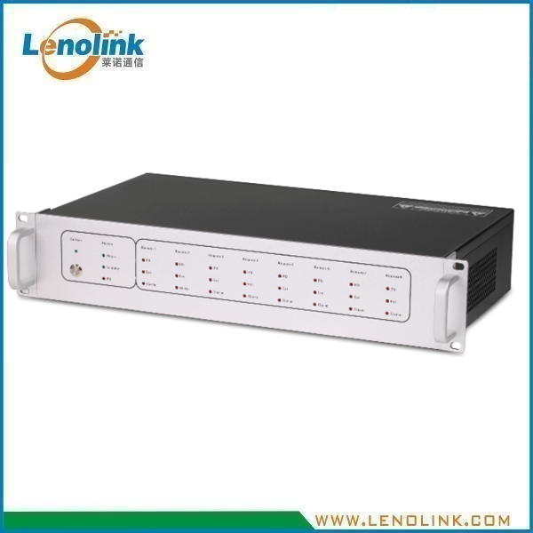
TETRA Fiber Optical Digital Repeater Master Unit (MU) | 450–455 MHz / 460–465 MHz
Product Model: LC7C00A
Applications
- Distributed TETRA coverage systems
- TETRA public safety communication networks
- Transportation and railway communication systems
- Airport and industrial communication networks
- Large buildings and indoor coverage systems
- Tunnels and other RF shadow areas
- Critical infrastructure communication systems
The Lenolink TETRA Fiber Optical Digital Repeater Master Unit (MU) is designed to interface with a TETRA base-station RF source and distribute RF signals to remote units (RUs) through an optical fiber link. The MU supports fiber transmission distances of up to 10 km, enabling remote units to be deployed away from the central equipment location.
Typical System Configuration
The MU is positioned at the central equipment side of the distributed coverage system. It interfaces with the TETRA base-station side and connects to remote units through optical fiber. The remote units then provide RF coverage through local antennas.
Recommended website diagram caption: TETRA Base Station → MU → Optical Fiber → RU → Antenna → Coverage Area
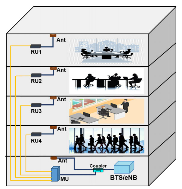
The MU is installed at the central equipment side, while RUs can be deployed in remote coverage areas through optical fiber.
Product Summary
The Lenolink LC7C00A TETRA Fiber Optical Digital Repeater Master Unit (MU) serves as the central RF and optical interface of a fiber-fed TETRA distributed coverage system. It interfaces with the TETRA base-station RF source and distributes RF signals to remote units (RUs) through single-mode optical fiber.
Key Specifications
Key RF & Optical Specifications
| Parameter | Specification |
|---|---|
| Product Type | TETRA Fiber Optical Digital Repeater – Master Unit |
| Model | LC7C00A |
| Uplink / Rx Frequency | 450–455 MHz |
| Downlink / Tx Frequency | 460–465 MHz |
| RF Bandwidth | 5 MHz per link |
| Max. Non-Destructive RF Input Power | 10 dBm |
| UL RF Output Power | −10 ± 2 dBm |
| MU Gain | 0 ± 3 dB |
| Manual Adjustable Attenuation | 0–10 dB |
| VSWR | ≤1.5 |
| System Delay | ≤5 μs |
| Fiber Type | Single Mode |
| Optical Connector | 4 × FC/APC |
| Optical Output Power | +3 ± 3 dBm @ 1550 nm |
| Optical Receiver Sensitivity | [confirm] |
| Transmission Distance | ≤10 km |
Mechanical & Environmental Specifications
| Parameter | Specification |
|---|---|
| RF Impedance | 50 Ω |
| RF Connector | 1 × N-Female Duplex Port |
| Operating Temperature | −20°C to +55°C |
| Relative Humidity | ≤85% |
| Power Supply | AC 220 V, 50/60 Hz |
| Power Consumption | ≤30 W |
| Application | Indoor, IP30 |
| Dimensions | 485 × 350 × 90 mm |
| Weight | ≤6 kg |
| Mounting | 19-inch 2U Rack Mount |
| Local Control | USB Interface / Wi-Fi Hotspot |
Key Features
- TETRA 450–455 MHz uplink/Rx and 460–465 MHz downlink/Tx operation
- 5 MHz RF bandwidth
- Optical fiber transmission distance up to 10 km
- Single-mode fiber interface
- 4 × FC/APC optical connectors
- 1 × N-Female duplex RF port
- 0–10 dB manually adjustable attenuation
- VSWR ≤1.5
- System delay ≤5 μs
- 19-inch 2U rack-mount chassis
- Indoor IP30 application
- USB interface or Wi-Fi hotspot for local control
Technical Advantages
Fiber-Based Remote Coverage
The MU converts and distributes RF signals through an optical fiber architecture, allowing remote units to be deployed away from the central equipment location.
Up to 10 km Transmission Distance
The supplied specification identifies a maximum transmission distance of ≤10 km, supporting distributed coverage architectures where remote units must be separated from the MU.
TETRA Band Configuration
The specified RF configuration supports 450–455 MHz uplink/Rx and 460–465 MHz downlink/Tx operation.
Adjustable RF Level
Manual attenuation of 0–10 dB provides a practical adjustment range for RF level management during system commissioning.
Low System Delay
A specified system delay of ≤5 μs helps maintain timing performance in distributed RF coverage applications.
Rack-Mount Integration
The 485 × 350 × 90 mm chassis is specified as a 19-inch 2U rack-mount unit for indoor equipment-room deployment.
Local Management
Local control is specified through a USB interface or Wi-Fi hotspot, providing convenient commissioning and maintenance access.
Working Principle
The MU receives RF signals from the TETRA base-station side and interfaces the RF signal with the optical fiber transmission network. The optical link carries the signal to remote units (RUs), where the RF signal is converted back for local antenna distribution. Uplink signals travel in the reverse direction from the coverage area toward the base-station side.
Why Choose Lenolink TETRA Fiber Optical Repeater MU?
1. Complete TETRA Fiber Coverage Architecture
Lenolink provides RF and optical components for distributed TETRA coverage systems, from central MU equipment to remote RF coverage units.
2. 10 km Fiber Transmission Capability
The LC7C00A supports fiber transmission distances of up to 10 km, enabling flexible deployment of remote units in large or geographically distributed facilities.
3. 19-inch 2U Rack Integration
The compact 2U chassis is designed for installation in standard 19-inch equipment racks and communication cabinets.
4. Flexible RF Level Adjustment
0–10 dB manual attenuation allows installers to optimize RF levels during system commissioning.
5. Multi-RU Optical Architecture
Four FC/APC optical interfaces support distributed remote-unit architectures.
6. Project-Based Customization
Lenolink can evaluate project-specific requirements including frequency configuration, number of RUs, fiber distance, RF levels, optical interfaces and mechanical integration.
Frequently Asked Questions
Q: What is a TETRA Fiber Optical Digital Repeater MU?
It is the Master Unit used at the central equipment side of a fiber-fed TETRA distributed coverage system. It interfaces with the base-station side and connects to remote units through optical fiber.
Q: What frequency does the MU support?
The supplied specification lists 450–455 MHz for uplink/Rx and 460–465 MHz for downlink/Tx.
Q: What is the RF bandwidth?
The supplied specification lists a 5 MHz bandwidth.
Q: What is the maximum transmission distance?
The supplied specification lists a transmission distance of ≤10 km.
Q: What optical fiber is used?
The specification identifies single-mode fiber.
Q: What optical connectors are provided?
The specification lists 4 × FC/APC optical connectors.
Q: What RF connector is used?
The specification lists 1 × N-Female duplex RF port.
Q: Can the RF attenuation be adjusted?
Yes. Manual adjustable attenuation is specified as 0–10 dB.
Q: What is the system delay?
The specified system delay is ≤5 μs.
Q: What is the mounting format?
The unit is specified as a 19-inch 2U rack-mount chassis.
Q: What are the environmental conditions?
The specified operating temperature is −20°C to +55°C, with relative humidity ≤85%. The application is indoor IP30.
Q: How many remote units can the LC7C00A support?
The LC7C00A is designed for fiber-fed distributed coverage architectures. The actual number of remote units depends on the optical architecture, system configuration and project requirements. Please contact Lenolink for system-level evaluation.
Q: What is the difference between the MU and RU?
The Master Unit (MU) is installed at the central equipment side and interfaces with the TETRA base-station RF source and optical fiber network. The Remote Unit (RU) is deployed in the target coverage area and converts the optical signal back to RF for local antenna distribution.
Q: Can Lenolink customize the system?
Lenolink can evaluate project-specific RF, optical, mechanical and system integration requirements based on the customer’s coverage architecture.
Request a Customized TETRA Coverage Solution
For a customized TETRA fiber optical repeater solution, please provide:
- Required TETRA frequency band
- Uplink and downlink frequency configuration
- Number of remote units
- Required fiber transmission distance
- RF input/output level requirements
- Optical connector and fiber requirements
- Coverage area and application environment
- Rack or cabinet requirements
Lenolink RF engineers can evaluate the project requirements and propose a suitable TETRA distributed coverage solution.
Contact: info@lenolink.com